(UPDATED 5.4.2013)
This is my insect robot project. I am actually writing this as I am building my robot from the spare parts since its always best to document while doing something so you can have the accurate information from memory that is fresh. When I started this project I was (and still am) incredibly broke like every other student so I was not sure how I was going to make/start my project let alone finish but I got the spare parts for this project from our course mentor Tero Karvinen.
The parts that I am going to use for this project are
– The Arduino Uno MicroController
– Ultrasound sensor (HC-SR04)
– Two servos (both of them are HC-311 models)
– iPhone 5 box (R.I.P. Steve Jobs, sorry for making fun of your phones)
– Jumper wires
– Roll of metal
– BreadBoard
– Ducktape (lol)
– Glue
The aim of the project is to create and program an insect robot that would walk and stop if and object comes in front of it and if I have time to program it to change direction if object is in front of it. The hardest part of this project was and still is that I don’t have sufficient amounts of money to buy decent hardware, tools or anything else for that matter to make anything smart even though I am staunch enemy of making excuses but in this example this is the unfortunate reality but I did manage to get a good project all in all.
What I did was that I put the Arduino microcontroller along side with all the necessary hardware inside the iPhone box and I programmed the Arduino to give signals to the servos so that the servos would move the metal pieces that I glued to them, so the whole thing would look like it was walking. The problem I encountered in this project was that how to program this thing so it would move forward.
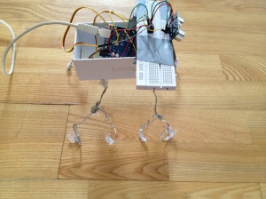
The problem arises with the servos. How am I to program this thing so it would walk forward when the legs are made of static metal/copper/tin bits not to mention to move direction. Because the project is low budget, the legs are made of solid metal, meaning that this Frankenstein monster does not have knees to lift up, so I had to program this thing to somehow push itself forward. I did found some tips from the book “Make: Arduino and bot gadgets” but I thought to make this thing look more like it was built by me so I created something that is not pretty to watch but it works (on some level). Below is the picture I took from the side of the robot
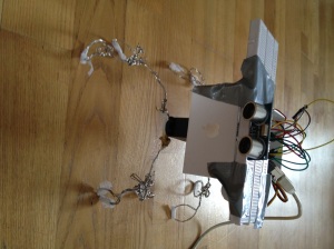
As you can see in the picture, that I have put some tape under the insects metal legs so it would be able to push itself forward. Without the tape this thing would slip all over the floor and not go anywhere because the metal would not be able to push on solid wood floor. I also was not able to have batteries on board this insect because the legs are very fragile and the legs would just collapse under the pressure. The best method would have been to buy some solid tin or copper tubes but then again this was supposed to be a personal project so the solution was not bad. I only regret that I did not buy a soldering gun to solder the legs to the servos. Anyway the functionality of this robot is just to walk and stop for 5 seconds if something comes in front of it (more than 20 cm closer) and continue to walk forward if the object has moved that was in front of it. Yes I know it is a bit silly, because if a wall is in front of it, it would just stand in front of it. Below is another picture from the front side of it.
You can see from the pictures that I duck taped the breadboard on top the the box and attached the ultrasound sensor on top of it. If you want to have more info about both the functionality of the servos and sensors please look for my previous assignments or go to the top of this post for the datasheets. Below is the code
#include <Servo.h> // Library
#define trigPin 8#define echoPin 9
Servo servo1;
Servo servo2; // The making of servo variable
void setup() {
Serial.begin (9600);
pinMode(trigPin, OUTPUT);
pinMode(echoPin, INPUT);
servo2.attach(12);
servo1.attach(11); // Attach variable to pin 11
}void loop() {
int duration, distance;
digitalWrite(trigPin, HIGH);
delayMicroseconds(1000);
digitalWrite(trigPin, LOW);
duration = pulseIn(echoPin, HIGH);
distance = (duration/2) / 29.1;if (distance <= 10){
delay(5000);
}else {
servo1.write(20); // move the servo with distance
servo2.write(120); // move the servo with distance
delay(1000);
servo1.write(10);
servo2.write(50);
delay(1000);
servo1.write(30);
servo2.write(120);
}
}
Unfortunately as I am writing this and going forward with my project, the legs of the robot have collapsed. I just glued it together so I am not sure how it will turn out later. Below is the video from my previous advancement few hours ago before I broke the robot.
I promise to upload the new video if I get my robot to walk again. By the way, something that I forgot to add in the beginning of my course posts was the link to the existing other peer links in my same class. Here is the link to my course mentors site
http://terokarvinen.com/2012/aikataulu-prototyypin-rakentaminen-bus4tn007-3-kevat-2013#comment-19365
Scroll down to see other people with their own projects in this course. I also did not manage to get the insect up and running since the glue simply is not enough for the legs like that, because I did not attach the legs properly around the servo wings. I will try to make a better project later with more ambitious plans with better equipment.
References:


![IMG_0102[1]](https://kuroshfarsimadan.files.wordpress.com/2013/02/img_01021.jpg?w=300&h=225)
![IMG_0103[1]](https://kuroshfarsimadan.files.wordpress.com/2013/02/img_01031.jpg?w=300&h=225)
![IMG_0105[1]](https://kuroshfarsimadan.files.wordpress.com/2013/02/img_01051.jpg?w=300&h=225)